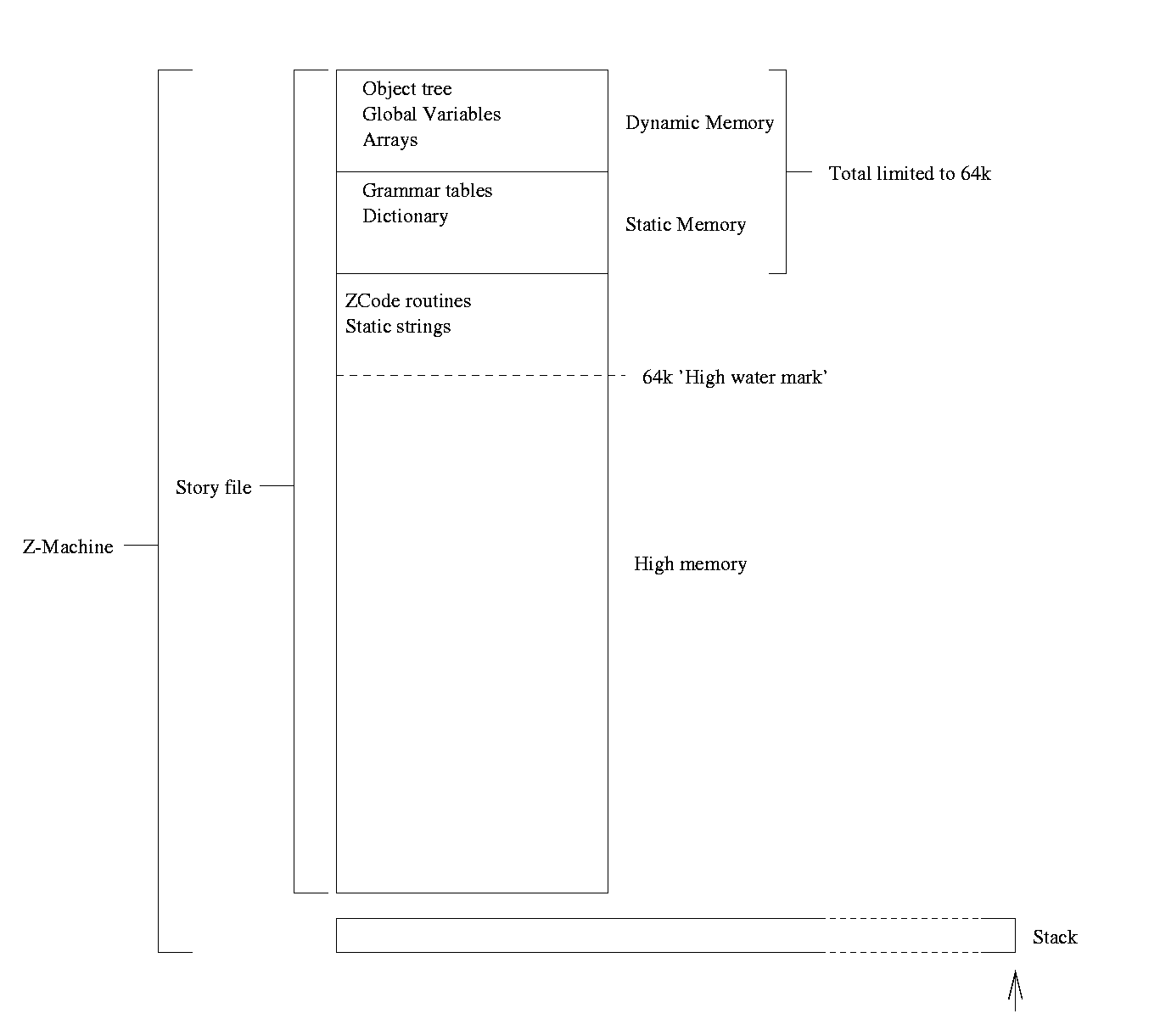
Figure 1 - design of the Z-Machine
This section begins with a brief discussion of pre-existing bytecode interpreters that are in current practicle use. Although the literature is full of articles discussing improvements and modifications that can be made to bytecode languages, it is remarkable poor in articles discussing the design of the languages themselves. This discussion will focus on zcode, one of the earliest examples of a portable bytecode language, and the byte code used by Moscow ML (itself a variant of that designed for Caml light). Tied up with the definition of the bytecode language is the definition of the virtual machine it will run under.
ZCode was designed by the company Infocom in 1979 and was designed to allow the cross-platform execution of text adventure games. Of particular concern to its designers was the design of the target platforms. The home computers that were emerging at that time were very limited in terms of memory, processor power and permanent storage space. To solve these problems, some complex operation were designed to be executed by the interpreter (notably the parsing of an input string), and the language incorporates several special-purpose structures for their support (dictionaries and grammar tables).
Briefly, ZCode runs on a virtual machine called the Z-Machine. This is a virtual 16-bit computer, which, owing to its long history of adaptations to improving computer hardware, has a complex structure. Version 8 is the most recent revision of the Z-Machine (although this revision was created by Graham Nelson after Infocom had ceased trading). Its architecture specifies three memory areas - 'Dynamic' memory, whose initial contents are specified in the file, but which may be changed at runtime, 'Static' memory, which follows dynamic memory and may not be changed, and 'High' memory, which follows the Static memory and may break the 64k boundary that is imposed on Static and Dynamic memory. In games compiled using Inform, dynamic memory is used for storing the object tree, object properties, global variables and arrays. Static memory stores various constant tables, and high memory contains the code and any static strings. The design of Z-Code really prohibits anything apart from strings and code being stored in high memory, as regions beyond the 64k marker do not have suitable load/storage commands in the Z-Code language, and are accessed using a special 'packed format' address (a 16-bit value), which is transformed by a formula to find the real address. The formula has tended to change between Z-Machine versions, but in version 8, it is simply the packed value multiplied by 8.
Figure 1 - design of the Z-Machine
Z-Machine instructions that take operands, for example add, can take their operands as constants or variables. Local variables, numbers 1-15, are allocated by the Z-Machine onto the stack when a routine is entered. Global variables, numbers 16-255 are allocated in dynamic memory, and the special variable number 0 can be used to refer to the number on the top of the stack. This design takes the business of allocating space for variables away from the compiler, but imposes limits on the number of variables that can be sensibly maintained. The Z-Machine has no registers and no accumulator; often bytecode languages are written to just manipulate the stack. This design style makes the design of compilers easier, as stack maintainance is the responsibility of the interpreter.
A Z-Code program is divided up into routines that may be accessed using the call directive. A routine is accompanied by a set of data that details things like the number of local variables. Branch operations are restricted to inside the routine.
Z-Code provides many types of instructions, which can be broadly placed into several groups:
The Z-Machine Standards Document[8] goes into far more detail about the Z-Machine's design, and I will not continue to discuss the minutae of the machine's design. It does, however, have one noteworthy feature - it can save complete details of its internal state to a file (dynamic memory, the stack and the current program counter), and restore that state on demand. This is a feature that is almost unique on this low-level, and which is very applicable for operating systems such as PalmOS, which requires such a state save when the user switches applications.
Moscow ML[9] is an implementation of standard ML based around Caml Light[10]. Design documentmentation for these languages does not seem to be readily available, so this discussion is based on analysis of the source code of Moscow ML 2.00. The bytecode was originally designed as an intermediate code between the ML compiler and interpreter, but is now also employed as a format for pre-compiled programs, as well as the format which the Moscow ML bootstrap compiler is written in.
The bytecode in Moscow ML is very obviously of an ad-hoc design. Each code is represented using one byte followed by a variable amount of data. The 'virtual machine' used by Moscow ML consists of a program counter, a stack and an accumulator. (Caml Light, for contrast has two stacks - one for arguments and one for return values). Arithmetic operators use the accumulator and the value on top of the stack, and store their results back into the accumulator.
The accumulator is a 32-bit int (actually, a long int, but it is apparent that the designers intended this to be 32-bits), and the stack is a list of 32-bit ints. The design of the stack is full-descending, although this is never exposed to the bytecode. The bytecode tends to use multiple instructions rather than arguments, possibly for reasons of performance (saving a read of an argument), but this means that the list of codes is very long. For instance, there are 8 different ACC commands - these commands set the accumulator to a value on the stack. ACC0 sets the accumulator to the top value (no popping is performed), to ACC7, which sets the accumulator to the value seventh from the top of the stack. This design may increase execution speed, but it starts to become limiting.
The bytecode commands employed by Moscow ML fit into the same categories as the ZCode commands, although there are multiple varieties of some commands (such as ACC, and also many different types of arithmetic operator - ADDINT, SMLADDFLOAT, and SMLADDINT, for instance). Overall, much of its design may be too limiting for the design of this bytecode.
The virtual machine's design is based around Z-Code, and also the memory models used in current computers. The memory has addresses from 0x0 to 0xfffffff (4 gigabytes), but no address can be accessed until memory has been allocated to that space. The bytecode program itself is stored outside that memory, and so cannot be altered while running. The bytecode program may contain an amount of 'static' memory, which is placed beginning at virtual address 0x0. It may also contain some pre-initialised settings for dynamic memory - this is placed after the static memory ends. It may also request that more memory be allocated later on.
Many current processors have a 32-bit address bus, and are most efficient at reading values that are stored aligned to a 4-byte boundary. 4-byte values will be referred to as words from now on. Static and dynamic memory size must be a multiple of 4, and 32-bit and higher values must be aligned to a word boundary. This design descision also eases the design of the interpreter for processors with these constraints.
Also present is a stack, which is also kept seperate from the main memory, and is used to store local variables, routine return addresses and intermediate values in calculations. In a secure implementation, the interpreter will check that a routine does not attempt to leave its stack 'frame', that is, pop values that come before its return address.
There is no accumulator or registers as such - all values being processed are stored in dynamic or static memory, or on the stack. Arguments to an operation that uses stack values will use a short notation that is faster to process than the notation used to store memory addresses.
The tables here indicate the instruction, the number of arguments and a suggested syntax for a disassembly. An instruction may take arguments, which can be a constant ('immediate') value, a reference to the top of the stack (which is popped, or pushed if a destination argument), a reference to a local variable, a direct reference to a memory location or an indirect reference to a memory location. When manipulating the stack, values are popped from left to right.
For example, the instruction ADD (stack) (stack) -> (stack) will pop two values from the stack, compute the result, and push the answer onto the top of the stack. The other addressing modes are covered more fully in the section on bytecode encoding.
Keeping to the categories outlined in the analysis of ZCode design above, the instructions supported will be as follows:
| Instruction | No. of Arguments | Disassembly syntax | Description |
Integer instructions |
|||
| MOVE | 2 | MOVE a -> b | Copies a 32-bit value from one location to another. The operation MOVE (stack) -> (stack) is special in that rather than being a no-op, it doubles up the value on top of the stack. |
| MOVEB | 2 | MOVEB a -> b | Copies an 8-bit value from one location to another. This copies the least significant 8 bits of a to the least significant 8 bits of b. Neither a or b have to be word aligned |
| NEGATE a -> b | 3 | NEGATE | Negates a and stores it in b |
| NOT | 3 | NOT | Does a bitwise NOT on the value on top of the stack |
| ADD | 0 | ADD | Pops two values from the stack, adds them and pushes the result |
| SUBTRACT | 0 | SUBTRACT | Pops two values from the stack, subtracts the topmost from the other and pushes the result |
| MULTIPLY | 0 | MULTIPLY | Pops two values from the stack, multiplies them and pushes the result |
| DIVIDE | 0 | DIVIDE | Pops two values from the stack and divides the second by the first and pushes the result |
| MODULO | 0 | MODULO | Pops two values from the stack and divides the second by the first and pushes the remainder |
| AND | 0 | AND | Pops two values from the stack, performs a bitwise AND on them and pushes the result |
| OR | 0 | OR | Pops two values from the stack, performs a bitwise OR on them and pushes the result |
| XOR | 0 | XOR | Pops two values from the stack, performs a bitwise XOR on them and pushes the result |
| NAND | 0 | NAND | Pops two values from the stack, performs a bitwise NAND on them and pushes the result |
| NOR | 0 | NOR | Pops two values from the stack, performs a bitwise NOR on them and pushes the result |
| NXOR | 0 | NXOR | Pops two values from the stack, performs a bitwise NXOR on them and pushes the result |
| LSL | 0 | LSL | Pops two values from the stack, and does a logical shift left of the second value by the number of bits specified by the first value, then pushes the result. |
| LSR | 0 | LSR | Pops two values from the stack, and does a logical shift right of the second value by the number of bits specified by the first value, then pushes the result. |
| ASR | 0 | ASR | Pops two values from the stack, and does an arithmetic shift right of the second value by the number of bits specified by the first value, then pushes the result. |
| ROR | 0 | ROR | Pops two values from the stack, and does a rotate right of the second value by the number of bits specified by the first value, then pushes the result. |
| LE | 0 | LE | Pops two values from the stack. If the second is less than or equal to the first, pushes 1, otherwise pushes 0. |
| LT | 0 | LT | Pops two values from the stack. If the second is less than the first, pushes 1, otherwise pushes 0. |
| GT | 0 | GT | Pops two values from the stack. If the second is greater than the first, pushes 1, otherwise pushes 0. |
| GE | 0 | GE | Pops two values from the stack. If the second is greater than or equal to the first, pushes 1, otherwise pushes 0. |
| EQ | 0 | EQ | Pops two values from the stack. If the second is equal to the first, pushes 1, otherwise pushes 0. |
| NE | 0 | NE | Pops two values from the stack. If the second is not equal to the first, pushes 1, otherwise pushes 0. |
| NZ | 0 | NZ | Pops one value from the stack. If the value is equal to 0, pushes 0, otherwise pushes 1 |
| TABLE | variable | TABLE a <- b c d ... | Stores the values b, c, d, etc into a. This opcode is not sensible when a is a variable (or constant, but that condition is specified elsewhere in this docment). When a is a memory location, values are stored consecutively from the location referred to by a, starting with b. When a is the stack, the values are pushed in order, starting with b (so that the last value is on the top of the stack). |
Floating-point |
Each of these has a varient for IEEE single-precision[12]
(32-bit) and IEEE double-precision[12] (64-bit)
calculations. The single-precision versions are postfixed
'S', and the double-precision version 'D' These instructions are based upon the ARM floating point instructions[11]. Note that double-precision instructions need twice as much data as single precision instructions - in order to achieve this, each argument is doubled up. That is, the double equivalent of MOVES a -> b would be MOVED a,b -> c,d. Also note that special behaviour is required when storing to the stack - the values should be stored in reverse order, so that they can be correctly read with a stack operation later - ie, MOVED a,b -> (stack),(stack) should restore the values of a,b when MOVED (stack),(stack) -> a,b is executed. |
||
| MOVE(S|D) | 2 | MOVE(S|D) a -> b | Stores a in b |
| NEGATE(S|D) | 2 | NEGATE(S|D) a -> b | Stores -a in b |
| ABSOLUTE(S|D) | 2 | ABSOLUTE(S|D) a -> b | Stores |a| in b |
| ROOT(S|D) | 2 | ROOT(S|D) a -> b | Stores the square root of a in b |
| LN(S|D) | 2 | LN(S|D) a -> b | Stores the natural log of a in b |
| SINE(S|D) | 2 | SINE(S|D) a -> b | Stores the sine of a (radians) in b |
| COSINE(S|D) | 2 | COSINE(S|D) a -> b | Stores the cosine of a (radians) in b |
| TANGENT(S|D) | 2 | TANGENT(S|D) a -> b | Stores the tangent of a (radians) in b |
| ARCSINE(S|D) | 2 | ARCSINE(S|D) a -> b | Stores the arctangent of a in b (radians) |
| ARCCOSINE(S|D) | 2 | ARCCONSINE(S|D) a -> b | Stores the arctangent of a in b (radians) |
| ARCTANGENT(S|D) | 2 | ARCTANGENT(S|D) a -> b | Stores the arctangent of a in b (radians) |
| ADD(S|D) | 3 | ADD(S|D) a b -> c | Stores a+b in c |
| SUBTRACT(S|D) | 3 | SUBTRACT(S|D) a b -> c | Stores a-b in c |
| MULTIPLY(S|D) | 3 | SUBTRACT(S|D) a b -> c | Stores a*b in c |
| DIVIDE(S|D) | 3 | DIVIDE(S|D) a b -> c | Stores a/b in c |
| MODULO(S|D) | 3 | DIVIDE(S|D) a b -> c | Stores a%b in c |
| POWER(S|D) | 3 | POWER(S|D) a b -> c | Stores a raised to the power of b in c |
| CONVITF(S|D) | 2 | CONVITF(S|D) a -> b | Converts 32-bit integer a to floating point number b |
| CONVFTI(S|D) | 2 | CONFFTI(S|D) a -> b | Converts floating point number a to 32-bit integer b. a is rounded to the nearest integer. If a is out of the acceptable range for integer numbers, b is set to 0x8000000 (-214748368, the most negative possible integer - this is also considered an out of range value for a). |
| CONVSTD | 2 | CONFSTD a -> b | Converts short floating point number a to double floating point number b. |
| CONVDTS | 2 | CONFDTS a -> b | Converts double floating point number a to short floating point number b. b is set to NaN if a cannot be represented. |
Table 1 - arithmetic operations
These operations handle the allocation and deallocation of memory. Note that load/store operations are handled by the data transfer instructions (MOVE, MOVES, MOVED) with memory address arguments. Unless stated otherwise, all arguments are 32-bit integers.
| Instruction | No. of Arguments | Disassembly syntax | Description |
| ALLOCATE | 2 | ALLOCATE a -> b | Allocates a bytes, and stores the position of the start of allocated space in the memory map in b. b will be set to 0 if the memory could not be allocated |
| REALLOCATE | 3 | REALLOCATE a b -> c | Reallocates the memory starting at a (which must be an address returned by ALLOCATE or REALLOCATE), to be size b bytes. The new address of the memory will be stored in c, and the old address, if different, will become invalid. |
| DEALLOCATE | 1 | DEALLOCATE a | Deallocates the memory at a, which must be an address returned by ALLOCATE or REALLOCATE. |
Table 2 - memory operations
These instructions are synonyms for the MOVE* instructions.
| Instruction | No. of Arguments | Disassembly syntax | Description |
| PUSH | 1 | PUSH a | This instruction is equivalent to MOVE a -> (stack) |
| POP | 1 | POP a | This instruction is equivalent to MOVE (stack) -> a |
| PULL | 0 | PULL | This instruction removes the top value from the stack and discards it |
| INCR | 0 | INCR | This instruction increases the value on the top of the stack by one |
| DECR | 0 | DECR | This instruction decreases the value on the top of the stack by one |
Table 3 - stack operations
As for ZCode, these instructions also serve as the comparason operators. All branch locations are a 32-bit twos complement number, and they represent an offset from the location of the branch instruction. The comparason operators listed here are the 32-bit integer versions. All of the comparason operations have floating point equivalents, their names being formed by postfixing S or D to their integer equivalent (as for the floating point operations).
| Instruction | No. of Arguments | Disassembly syntax | Description |
| JUMP | 1 | JUMP -> a | Adds a to the program counter |
| BRANCHZ | 2 | BRANCHZ a -> b | If a is zero, then add b to the program counter |
| BRANCHNZ | 2 | BRANCHNZ a -> b | If a is non-zero, then add b to the program counter |
| BRANCHEQ | 3 | BRANCHEQ a b -> c | If a is equal to b, then add c to the program counter |
| BRANCHNE | 3 | BRANCHNE a b -> c | If a is not equal to b, then add c to the program counter |
| BRANCHGE | 3 | BRANCHGE a b -> c | If a is greater than or equal to b, then add c to the program counter |
| BRANCHGT | 3 | BRANCHGT a b -> c | If a is greater than b, then add c to the program counter |
| BRANCHLT | 3 | BRANCHLT a b -> c | If a is less than b, then add c to the program counter |
| BRANCHLE | 3 | BRANCHLT a b -> c | If a is less than or equal to b, then add c to the program counter |
Floating point exceptions |
These instructions detect errors in previous floating point computations by inspecting the value. | ||
| BRANCHNAN | 2 | BRANCHNAN a -> b | Add b to the program counter if a is NaN (Not a Number) |
| BRANCHINF | 2 | BRANCHINF a -> b | Add b to the program counter if a is Inf (Infinity) |
| BRANCHINFP | 2 | BRANCHINFP a -> b | Add b to the program counter if a is +Inf (positive Infinity) |
| BRANCHINFN | 2 | BRANCHINFN a -> b | Add b to the program counter if a is -Inf (negative Infinity) |
Table 4 - Branch operations
These operations deal with entering and leaving 'routines'. These correspond to functions in a high-level language. The 'TRAP' and 'TRAPPOINT' instructions allow for a language to implement exceptions, both generated by the program, and generated by internal errors (such as floating point errors).
| Instruction | No. of Arguments | Disassembly syntax | Description |
| CALL | 2 | CALL a b | Saves the current position and enters routine number a. b arguments should be on the stack, which are stored in variables V2..V(b+1). If a routine has less variables than are passed on the stack, this is a runtime error and execution should halt. |
| RETURN | 0 | RETURN | Exits the current routine, and return to the instruction after the CALL operation that initialised the routine. One value is popped from the stack frame of the routine that is being returned from, and this value is pushed onto the stack frame of the routine that is being returned to |
| RETURND | 0 | As for RETURN, but pops and pushes two values (this is required to return a double-precision number). The routine being returned to is expected to know that two values are being returned. | |
| TRAPPOINT | 3 | TRAPPOINT a -> b c | Stores a 'trappoint' on the stack. a is a 32-bit mask indicating which traps should return to this point if they are triggered. b is a jump offset - this jump is taken when a trap is triggered. c is set to a value specified by the TRAP statement that caused this trap. |
| TRAP | 2 | TRAP a b | a is a 32-bit integer, in the range 0-31. This commands triggers a trap, which causes the runtime system to return to any TRAPPOINT that has the bit corresponding to a set. Argument c of TRAPPOINT is set to b. |
| ONTRAP | 2 | ONTRAP a -> b | This function allows a routine to register cleanup handlers that deal with a trap that forces an exit from a function. a is a number, unique in that routine, that identifies this handler. b is a jump offset that indicates the location to branch to when a trap occurs. If a future ONTRAP has an identical value of a, this removes the effect of the present ONTRAP. If b is 0, the effect of the present ONTRAP is removed, and not replaced, otherwise the effect is to jump to the new value of b. |
| CALLREF | 3 | CALLREF a b c | As for CALL, except for argument c, which must be a
memory location, and which points to an argument modifier block,
which is used to modify the arguments read from the stack
before continuing with the CALL.
An argument modifier block consists of a list of word pairs, terminated by a pair with the value '0/0'. These pairs indicate that a particular argument should be set to a particular value - for example the pair '1/5' indicates that argument 1 should be set to the value 5. Note that these values are inserted and do not replace the original value, so in the previous example, the old argument 1 would become the new argument 2, the old argument 2 would become the new argument 3 and so on. This feature will be used by the compiler to implement higher-order functions. These arguments are assumed to be standard references, as generated by the compiler, which are memory pointers to blocks which have the first word set to a reference count. In order to avoid the garbage collector destroying these variables when the function returns, CALLREF should increase this value by 1 for each of the inserted arguments. |
Table 5 - Routine operations
There is only one miscellaneous operation allocated for this language:
| Instruction | No. of Arguments | Disassembly syntax | Description |
| SYSTEM | Variable, at least 1 | SYSTEM a (b c ... x) | This calls system routine number a with arguments b ... x. a is a 32-bit number indicating the system routine to use; the system routine numbers are defined elsewhere in this project. The intention of this operation is to allow the bytecode program to interact with the system it is running on (for example, a system routine could be called to print a string out) |
| NOP | 0 | NOP | This instruction does nothing |
| DUPLICATE | 0 | DUPLICATE | This instruction doubles up the value currently on top of the stack. |
| DUPLICATED | 0 | DUPLICATED | This instruction doubles up the two values currently on top of the stack. (IE, if the stack currently contains 0 1 2, after this operation, it contains 0 1 2 1 2) |
Table 6 - Miscellaneous operations
Due to the width of the address bus on many modern processors, reading memory in 32-bit chunks is generally much quicker than reading it a byte at a time. (Some processors, such as the ARM, have designed their instruction sets around this fact). Consequently, all instructions will be aligned to word addresses to take maximum advantage of these architectures (future systems may use 64-bit or 128-bit words - these systems may need further optimisation depending on their architecture and compiler designs). Where a value is intended to be read as a complete word, the value is little-endian. Note that operations on blocks 32-bits or larger must be to word-aligned locations (local variables and the stack are always kept word-aligned).
An instruction is encoded as a single byte indicating its type, followed by a variable number of bytes indicating its arguments, possibly followed by a selection of bytes and words that indicate more detail about its arguments (constants, for example)
For instructions that can take variable numbers of elements, the first argument byte indicates the number of following arguments (so these instructions are limited to a maximum of 255 arguments). Instructions which take a fixed number of arguments do not have this value. The rest of the arguments can have a value as follows:
| Value | Meaning |
| 0 | Pop argument value from stack (unless argument is a destination, in which case push the result onto the stack) |
| 1 | Read argument from absolute memory address (direct memory access) |
| 2 | Read argument from a memory address stored in a variable, and add a variable offset (indirect memory access) |
| 3 | Argument has a constant value |
| 4 | Argument is a symbolic reference |
| 5 | Argument is a local variable |
| 6-255 | Reserved (should never be used) |
Table 7 - Argument types
For argument values that require more information (1, 2, 3, 4 and 5), this information is encoded into two blocks that follow the instruction. The first of these blocks incorporates data that is represented by a single byte, and the second incorporates data that is represented by words (this block is word-aligned). The encoding for these types is as follows:
| Code | Values in byte block | Values in word block |
| 0 (pop from stack/push onto stack) | None | None |
| 1 (direct memory) | None | 1 word indicating memory address argument is to be read from |
| 2 (indirect memory) | 2 bytes indicating the variables to use. These can be 1 to indicate the value should be read from a memory address, 0 to indicate that the value is to be popped from the stack, 5 to indicate a constant value, or 8-255 to indicate a local variable. | 2 words corresponding to the 2 variable indicator. If the indicator is 1, these contain the address to read from, otherwise these should contain 0 |
| 3 (constant value) | None | 1 word for an integer value or an IEEE float. 2 words for an IEEE double. |
| 4 (symbolic reference) | n bytes to contain the (0-terminated) name of the symbol this references. This argument should only occur in a bytecode file that is intended for future linking to other bytecode files. The symbolic reference is replaced with a routine number, jump offset or memory location. | None |
| 5 (local variable) | None | 1 word indicating the variable number |
Table 8 - Additional data required by argument types
Values are pushed onto both blocks in a left to right manner, so if an instruction has (for example), one constant value, one indirect value and one stack value, the byte block will contain 2 bytes corresponding to the second argument, and the word block will contain 1 word corresponding to the constant followed by 2 words corresponding to the indirect value. The byte block will also contain some bytes of padding to ensure that the word block is word aligned (in this case 2, as the instruction uses 1 byte, followed by 3 bytes indicating the argument types, followed by the 2 bytes of the byte block. From this point, the next word aligned position is 2 bytes away)
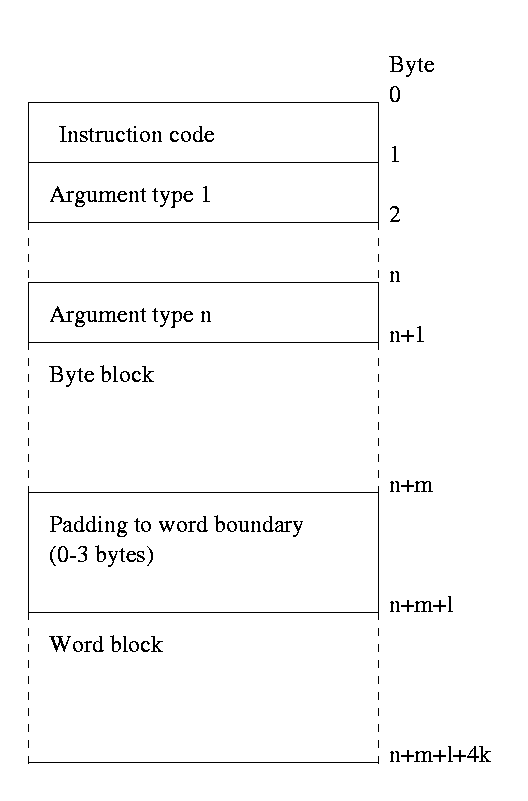
Figure 2 - layout of a typical instruction
Bytecode files have some additional information stored in them to initialise the static and dynamic memory areas, and to give information about the version of the file itself. All offsets are in bytes unless otherwise stated.
The files start with a header:
| Length | Description |
| 1 word | Revision of the bytecode standard this file requires. This document describes version 1.00, represented by a value of 100 in this word |
| 1 word | Offset from file start to the start of static data. This is initialised into memory starting at (virtual) location 0. |
| 1 word | Length of static data in words |
| 1 word | Length of dynamic data in words (the dynamic data follows immediately after the end of the static data) |
| 1 word | Offset from the start of the file to the start of code |
| 1 word | Offset from the start of the file to the routine table |
| 1 word | Highest routine number used by this file (unsigned) |
| 1 word | Offset from the start of the file to the symbol table (or 0 if no symbol table is present) |
Table 9 - Header stored in bytecode file
The routine table indicates the properties of routines that may be accessed using CALL. Execution begins by calling routine 0 (which can take no arguments), and ends when this routine returns. The routine table consits of a list of entries in the following format. The first entry describes routine 0, and successive entries describe successive routines. If a file is not intended to be run, routine 0 should reference offset 0.
| Length | Description |
| 1 word | Offset from start of file to routine start |
| 1 word | Number of local variables to allocate space for. Note that a variable containing an IEEE double needs two successive allocations. |
Table 10 - Format of an entry in the routine table
The symbol table is used to resolve references (argument type 6) at run- or link-time. A reference can either be to a routine or a memory location. The table consists of a list of entries, each with the following format. Memory references are dereferenced as direct memory accesses, and routine references are dereferenced as constants:
| Length | Description |
| 1 word | The routine number or the memory location this reference applies to. A memory location is an offset from the start of the file, and a routine number is as for call. |
| 1 word | The type of reference. This can be 0 to indicate a memory reference or 1 to indicate a routine reference |
| n bytes | A 0-terminated string indicating the name of this reference |
| n bytes | 0-3 bytes to pad to a word boundary |
Table 11 - Format of an entry in the reference table
Finally, the opcodes described in the previous section need to have numbers assigned:
| Opcode | Number |
Arithmetic operations |
|
| MOVE | 0 |
| MOVEB | 1 |
| NEGATE | 2 |
| NOT | 3 |
| ADD | 4 |
| SUBTRACT | 5 |
| MULTIPLY | 6 |
| DIVIDE | 7 |
| MODULO | 8 |
| AND | 9 |
| OR | 10 |
| XOR | 11 |
| NAND | 12 |
| NOR | 13 |
| NXOR | 14 |
| LSL | 15 |
| LSR | 16 |
| ASR | 17 |
| ROR | 18 |
| LE | 19 |
| LT | 20 |
| GT | 21 |
| GE | 22 |
| EQ | 23 |
| NE | 24 |
| NZ | 25 |
| TABLE | 26 |
| PULL | 27 |
| INCR | 28 |
| DECR | 29 |
Arithmetic operations (floating point) |
|
| MOVES | 32 |
| NEGATES | 33 |
| ABSOLUTES | 34 |
| ROOTS | 35 |
| LNS | 36 |
| SINES | 37 |
| COSINES | 38 |
| ARCSINES | 39 |
| ARCCOSINES | 40 |
| ARCTANGENTS | 41 |
| ADDS | 42 |
| SUBTRACTS | 43 |
| MULTIPLYS | 44 |
| DIVIDES | 45 |
| MODULOS | 46 |
| POWERS | 47 |
| CONVITFS | 48 |
| CONVFTIS | 49 |
| CONVDTS | 50 |
| MOVED | 64 |
| NEGATED | 65 |
| ABSOLUTED | 66 |
| ROOTD | 67 |
| LND | 68 |
| SINED | 69 |
| COSINED | 70 |
| ARCSINED | 71 |
| ARCCOSINED | 72 |
| ARCTANGENTD | 73 |
| ADDD | 74 |
| SUBTRACTD | 75 |
| MULTIPLYD | 76 |
| DIVIDED | 77 |
| MODULOD | 78 |
| POWERD | 79 |
| CONVITFD | 80 |
| CONVFTID | 81 |
| CONVSTD | 82 |
Memory operations |
|
| ALLOCATE | 96 |
| REALLOCATE | 97 |
| DEALLOCATE | 98 |
Branch operations |
|
| JUMP | 128 |
| BRANCHZ | 129 |
| BRANCHNZ | 130 |
| BRANCHEQ | 131 |
| BRANCHNE | 132 |
| BRANCHGE | 133 |
| BRANCHGT | 134 |
| BRANCHLT | 135 |
| BRANCHLE | 136 |
| BRANCHNAN | 137 |
| BRANCHINF | 138 |
| BRANCHINFP | 139 |
| BRANCHINFN | 140 |
Routine operations |
|
| CALL | 160 |
| RETURN | 161 |
| RETURND | 162 |
| TRAPPOINT | 163 |
| TRAP | 164 |
| ONTRAP | 165 |
| CALLREF | 166 |
Miscellaneous operations |
|
| SYSTEM | 224 |
| NOP | 225 |
| DUPLICATE | 226 |
| DUPLICATED | 227 |
Table 12 - Opcode numbers